
InSAR technology can measure millimeter-scale displacements of the ground and infrastructure using satellite radar imagery. However, there is an important limitation when interpreting these data: the satellite does not directly measure vertical and horizontal ground motion, but rather its projection onto the sensor’s line of sight.
Deriving the vertical and horizontal components of displacement requires a procedure known as InSAR displacement decomposition.
This process combines measurements from different acquisition geometries and relies on assumptions about the direction of motion. Problems arise when these assumptions do not match the actual ground displacement, as they can introduce significant errors into the results.
For example, an incorrect decomposition can lead to a landslide being interpreted as vertical subsidence, or to the deformation rate of a piece of infrastructure being overestimated or underestimated.
This article explains how InSAR displacement decomposition works, the assumptions commonly used, and its main limitations in civil engineering and geotechnical applications.
What is InSAR displacement decomposition?
InSAR displacement decomposition is the procedure used to derive displacement components in different spatial directions from satellite radar measurements.
The actual motion of a point on the ground can be described by three components: vertical, east–west, and north–south.
However, a radar satellite measures only the projection of that motion onto the direction connecting the sensor to the observed point, known as the line of sight (LOS).
For this reason, the vertical and horizontal displacement maps presented in many InSAR studies do not represent direct measurements of these components. They are the results of a decomposition process.
To understand how this procedure works, we first need to understand how a radar satellite observes the ground.
How does InSAR measure ground motion?
The satellite’s line of sight (LOS)
Each InSAR acquisition can be used to determine how far a point on the ground moves toward or away from the satellite along its line of sight.
To picture this, imagine a surveyor using a distance meter at a fixed position to measure the distance to a prism.
If the prism moves toward or away from the instrument, the motion can be detected. If it moves perpendicular to the observation direction, however, the distance changes very little, and the motion may go undetected.
The same principle applies to a radar satellite.
An InSAR measurement represents the projection of the actual displacement onto the line of sight, so the ability to detect motion depends on the direction in which it occurs.
Ascending and descending acquisition geometries
Radar satellites such as Sentinel-1 follow near-polar orbits and view the Earth’s surface from the side.
Images are acquired primarily from two geometries:
- Ascending geometry: the satellite travels approximately from south to north and looks eastward.
- Descending geometry: the satellite travels approximately from north to south and looks westward.
Each geometry provides a displacement measurement along its respective line of sight.
Combining the two observations provides two different measurement directions, giving us more information about ground motion.
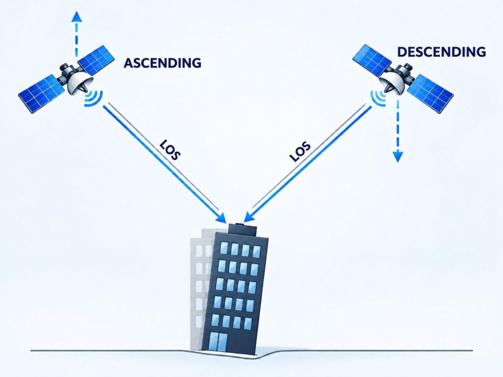
However, the acquisition geometry determines the sensitivity to displacement in each direction.
- Vertical motion: the vertical component is well observed. Satellites such as Sentinel-1 typically use incidence angles of approximately 30–45°, so their measurements capture a substantial proportion of subsidence and uplift.
- East–west motion: this component is also relatively well observed. The satellite’s side-looking geometry gives ascending and descending observations favorable sensitivity to displacement in this direction.
- North–south motion: this is the least well-observed component. Because the orbits are near-polar, displacement approximately along the satellite’s flight path makes only a small contribution to the LOS measurement. For a representative Sentinel-1 geometry, this contribution may be around 13%.
This difference in sensitivity is essential to understanding the capabilities and limitations of displacement decomposition.
How are vertical and horizontal displacements decomposed with InSAR?
To determine the three-dimensional motion of a point, we need to know its three components: vertical, east–west, and north–south.
With two acquisition geometries, ascending and descending, we have two independent measurements with which to determine a displacement with three components. InSAR decomposition therefore requires an additional assumption.
For more information on combining different displacement measurement technologies, see our article on integrating GNSS and InSAR.
The most common strategies are to assume that displacement is purely vertical, set the north–south component to zero, or use a reference frame aligned with the orientation of a slope or structure.
Decomposition assuming purely vertical motion
One of the simplest approaches is to assume that ground displacement occurs only in the vertical direction.
Under this assumption, a single acquisition geometry can be used to calculate vertical motion from the LOS measurement and the satellite’s incidence angle.
This strategy has traditionally been used in subsidence studies, where horizontal displacements are assumed to be negligible compared with vertical displacements.
However, when horizontal motion is present, projecting the LOS measurement onto the vertical axis can produce incorrect results.
Under these conditions, horizontal displacement may be interpreted as subsidence or uplift.
When two geometries are used and the actual motion is not strictly vertical, decomposition may yield horizontal components and propagate the error associated with that assumption into the results.
Decomposition assuming zero north–south displacement
One of the most widely used strategies combines ascending and descending acquisition geometries to derive the vertical and east–west components.
To solve the system, an assumption is imposed: north–south motion is zero.
This approximation is particularly reasonable when analyzing large areas where displacement may occur in different directions and the displacement mechanism at each point is unknown. In these cases, setting the north–south component to zero generally introduces the least error, because this direction is close to the direction of lowest sensitivity for satellites in near-polar orbits.
It also yields two displacement components that have a direct interpretation in many civil engineering problems.
Nevertheless, the assumption of zero north–south motion does not always reflect actual ground behavior.
If displacement has a substantial component in that direction, its effect may propagate into the estimated vertical and east–west components.
Although this is a common strategy, its validity therefore depends on the characteristics of the motion being analyzed.
Decomposition in reference frames adapted to slopes and infrastructure
In some applications, it is more appropriate to express displacement along directions related to the geometry of the terrain or a structure.
For example, on a slope, motion along the direction of maximum slope may be of interest. For a dam, wall, or dike, displacement perpendicular to the structure may be particularly relevant.
Local reference frames can be used in these cases.
One option is to retain the vertical axis and orient the horizontal axis perpendicular to the structure or slope, assuming that motion parallel to it is zero.
Another strategy uses a slope-oriented reference frame with three directions:
- Upwards: the uphill direction of maximum slope.
- Transverse: the direction parallel to the contour lines.
- Normal: the direction perpendicular to the slope surface.
In this system, the Transverse component can be assumed to be zero, meaning that motion is assumed to occur within the plane defined by the direction of maximum slope and the direction normal to the surface.
These strategies allow the decomposition to be adapted to the expected deformation mechanism.
As with the previous assumptions, however, the results depend on whether the assumed direction matches the actual ground motion.
Main limitations and errors in InSAR decomposition
The limitations of decomposition are primarily related to the observation geometry and the assumptions used to estimate the displacement components.
Even when LOS measurements are precise, an incorrect assumption can introduce errors into the resulting components.
The null direction, or blind direction, of the InSAR system
One of the most important concepts for understanding the limitations of displacement decomposition is the null direction.
This is the spatial direction to which both ascending and descending acquisition geometries are simultaneously insensitive.
If a point moves exactly in this direction, the projection of its motion onto both lines of sight is zero.
For a typical Sentinel-1 geometry, the null direction is close to north, with a slight upward inclination of approximately 10°.
This explains why sensitivity to north–south motion is particularly low.
Furthermore, any displacement with a component along the null direction contains a part that cannot be observed through the two LOS measurements.
How this unobservable component affects the results depends on the assumption used in the decomposition.
Displacement can go completely undetected in both InSAR geometries if it occurs along the null direction. For Sentinel-1, this direction is close to the north–south axis.
What happens when the motion assumption is not satisfied?
As discussed above, decomposition requires assuming that a particular displacement component is zero or has a known value.
If the actual displacement does not satisfy this condition, however, systematic errors may arise in the estimated components.
Motion assumed to be zero does not disappear: its effect may be transferred to the other displacement components.
The magnitude of the error depends both on the omitted motion and on the orientation of the reference frame relative to the null direction.
Research by Detektia shows that when the direction along which motion is assumed to be zero is aligned with the satellite’s blind direction, the unobservable motion does not bias the other two estimated components.
This does not mean that the full three-dimensional displacement is recovered, as the component along the null direction still cannot be determined.
Conversely, when the chosen assumption is poorly oriented relative to the null direction, the error can propagate and be considerably amplified.
The influence of slope or infrastructure orientation
The orientation of the terrain or a structure can have a major influence on the reliability of a decomposition.
For structures oriented so that the motion of interest occurs along directions well observed by the satellite, decomposition can provide more robust results.
By contrast, when the expected displacement approaches the null direction, the observations contain less information about that motion.
This is particularly important when applying local reference frames to slopes, dams, dikes, or embankments.
Small orientation errors can produce substantial differences in the calculated components. In some configurations, error amplification factors can exceed 15.
Therefore, the orientation of the structure and the expected direction of motion must be considered before selecting a decomposition strategy.
Systematic errors and noise sensitivity
The research also distinguishes two different effects that can influence the results.
Systematic errors, or biases, arise when the assumed motion does not correctly represent the actual displacement.
Separately, noise in the LOS measurements can propagate and be amplified during decomposition.
This second effect becomes particularly important when the actual motion approaches the null direction.
Under these conditions, the projection of the displacement onto the lines of sight decreases, while measurement noise remains present.
As a result, the ratio of the deformation signal to noise can deteriorate significantly.
A decomposition can be affected both by the error associated with an incorrect assumption and by the low sensitivity of the observations to the displacement direction.
Examples of InSAR displacement decomposition in civil engineering
The limitations described above can have important consequences for interpreting deformation processes affecting the ground and infrastructure.
The following examples are synthetic scenarios that illustrate how assumptions and acquisition geometry influence the results.
The values correspond to a representative Sentinel-1 geometry with an incidence angle close to 39°.
A landslide interpreted as vertical subsidence
Consider a north-facing slope inclined at 30° that moves downslope at 10 mm/yr.
This motion has two main components:
- Northward displacement of approximately 8.7 mm/yr.
- Downward vertical displacement of 5 mm/yr.
If conventional decomposition is applied assuming zero north–south motion, the result may indicate subsidence of approximately 6.5 mm/yr, with no horizontal displacement.
In this case, the estimated vertical motion is approximately 30% greater than the actual value.
An incorrect decomposition assumption can lead to a landslide being interpreted as vertical subsidence, changing the diagnosis of the deformation process.
Horizontal displacement interpreted as subsidence and uplift
Now consider a slope undergoing horizontal displacement of 8 mm/yr eastward, with no vertical component.
If each acquisition geometry is used separately and its LOS measurement is projected onto the vertical axis, assuming purely vertical motion, the results may be opposite in sign.
In the example analyzed, the ascending geometry indicates apparent subsidence of approximately 6 mm/yr, while the descending geometry shows uplift of a similar magnitude.
Neither of these vertical motions is real, however. The displacement is horizontal.
When ascending and descending geometries yield vertical results of opposite sign under the assumption of purely vertical motion, this contradiction may be an indication of horizontal displacement.
The orientation of a dam or wall
For some structures, such as dams, dikes, or walls, displacement perpendicular to the structure may be particularly important.
When this direction is close to the east–west axis, typical Sentinel-1 geometries provide favorable observation conditions.
By contrast, when the motion of interest is predominantly north–south, it may be close to the null direction.
In that case, the displacement signal in the LOS measurements may be very small, and the results may become particularly sensitive to both errors in the assumptions and noise.
Thus, two structures with similar characteristics can differ significantly in the reliability of their InSAR results solely because of their orientation.
Cases where conventional decomposition performs well
Not all deformation processes pose the same difficulties.
In some cases of urban subsidence, embankment consolidation, or settlement associated with tunneling, motion may be dominated by the vertical component.
When this assumption reflects the actual behavior, conventional decomposition strategies can provide suitable results.
Satisfactory results can also be obtained when horizontal motion is predominantly east–west.
The key issue is whether an assumption is appropriate for the deformation mechanism and observation geometry of each project, rather than whether it is universally correct or incorrect.
Comparison table: InSAR decomposition risks and strategies by infrastructure type
| SITUATION | EXPECTED MOTION | RISK WITH THE DEFAULT APPROACH | RECOMMENDED APPROACH |
| Urban subsidence, consolidation on flat terrain | Vertical | Low | “Zero north–south” or “vertical + east–west” |
| East- or west-facing slope | Along the slope, east–west | Low–moderate | Local slope reference frame; check using the dashboard |
| North- or south-facing slope | Along the slope, north–south | High: sliding is interpreted as settlement | Local slope reference frame; check its alignment with the blind direction |
| Dams, dikes, railway embankments | Perpendicular or parallel to the axis | Depends on the orientation of the structure | Reference frame aligned with the structure; assess sensitivity before drawing conclusions |
| Walls and buildings undergoing rotation or tilting | Horizontal, in a specific direction | Moderate–high | Define the expected direction and check whether it is observable |
Research into the limitations of InSAR displacement decomposition
The limitations of decomposition have been investigated by the Detektia team, together with researchers from Universidad Politécnica de Madrid and the University of Jaén, in the scientific paper On the Limitations of InSAR Decomposition Imposed by Displacement Direction and Coordinate System, published in Remote Sensing in October 2026.
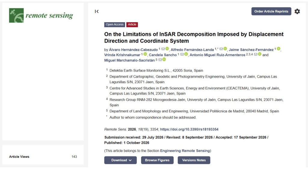
The study examines how the actual displacement direction, the coordinate system used, and the acquisition geometry influence errors in InSAR decomposition. It uses synthetic scenarios in which the actual displacement is known.
That motion is used to simulate the measurements that would be recorded in ascending and descending geometries, after which different decomposition methods are applied.
Comparing the results with the known displacement makes it possible to analyze the errors introduced by each strategy.
The study considers two reference frames: the geographic East–North–Vertical coordinate system and a local slope-oriented system.
Specifically, the research compares four decomposition strategies: zero-North, vertical–planimetric, slope-aligned, and null-direction-aligned decomposition.
The scenarios examined include motion with different vertical and horizontal components, predominantly north–south displacement, and local reference frames with different orientations.
In addition to evaluating systematic errors, the study examines how the different strategies affect sensitivity to noise in the observations.
The study also establishes a reproducible framework for anticipating decomposition errors based on the satellite acquisition geometry and slope orientation. These relationships have been implemented in Detektia’s interactive dashboard.
The results highlight the importance of selecting decomposition assumptions with the expected deformation mechanism and satellite geometry in mind.
A dashboard for analyzing InSAR displacement decomposition
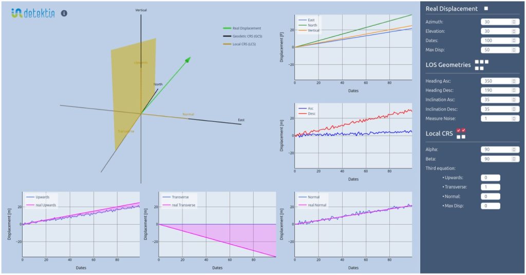
To help analyze these limitations, Detektia has developed an interactive dashboard for simulating different motion scenarios and examining how decomposition assumptions affect the results.
The tool allows users to enter the acquisition geometry of the ascending and descending observations and configure different displacement directions.
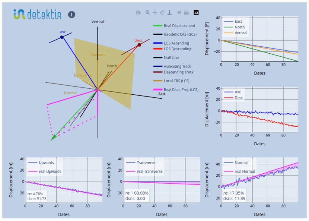
Using these parameters, the dashboard calculates the projections of the motion onto the lines of sight and applies different decomposition strategies. Its features include:
- Configuring the angles and acquisition geometry of the InSAR observations.
- Simulating true displacement in different directions.
- Visualizing the null direction for the selected geometry.
- Comparing different decomposition strategies.
- Analyzing the errors associated with the assumptions used.
- Assessing the influence of slope or infrastructure orientation.
This makes it possible to examine how the same deformation scenario can produce different results depending on the chosen reference frame and assumption.
The dashboard is designed as a tool for geometric sensitivity analysis, allowing users to investigate potential decomposition limitations before interpreting project results. Open Detektia’s InSAR decomposition dashboard.
Why understanding the limitations of InSAR decomposition matters
InSAR technology provides valuable information for monitoring ground and infrastructure deformation.
However, vertical and horizontal components derived through decomposition must be interpreted in light of the acquisition geometry and the assumptions used.
The existence of a null direction, reduced sensitivity to certain movements, and error propagation when the assumptions do not represent the actual displacement are fundamental considerations when assessing the reliability of the results.
Before interpreting an InSAR decomposition, it is therefore important to identify which displacement component has been assumed to be zero, check whether that assumption is compatible with the expected deformation process, and assess the orientation of the reference frame relative to the observation geometries.
Understanding how each displacement component was derived is just as important as having precise measurements.
To learn more about this technology, see our InSAR course for civil engineering applications.
Scientific reference
- Hernández-Cabezudo, Á.; Fernández-Landa, A.; Sánchez-Fernández, J.; Krishnakumar, V.; Sancho, C.; Ruiz-Armenteros, A.M.; Marchamalo-Sacristán, M. (2026). On the Limitations of InSAR Decomposition Imposed by Displacement Direction and Coordinate System. Remote Sensing, 18(19), 3354.
Attributions
- Cover image by vecstock on Magnific.
