SAR sensors make use of different frequency bands for data collection. Each of these band offers its own characteristics and possible applications. Combining data provided by SAR sensors with InSAR technology is possible to detect ground and infrastructure movements with millimeter accuracy.
In many cases, InSAR technology requires complex algorithms in order to generate accurate results. In this article we will talk about persistent scatterer interferometry (known as PSI or PS-InSAR) and distributed scattering interferometry (known as DSI or DS-InSAR) techniques.
The problem of radar backscattering
An optical image usually reveals information on an object’s composition, temperature, and other physical properties such as texture. On the other hand, SAR gives information on signal intensity, direction, amplitude, and phase.
The interaction of transmitted signals depends on the target’s structure and dielectric properties. When the radar waves from the satellite encounter an object, they are partially absorbed, scattered, and reflected.
Radar backscattering refers to the portion of radar energy that is reflected back to the radar antenna by a target object. When a radar signal from the satellite interacts with an object on earth, a portion of the signal is scattered back in the direction of the radar, and this backscattered energy is recorded by the radar.
The magnitude of the backscattered signal defines the brightness of a given pixel in the image. Hence the interpretation of synthetic aperture radar (SAR) images is not straightforward.
Radar backscattering is recorded by the radar and as a result, the interpretation of SAR images becomes a complex task.
SAR radiation is coherent, because the microwave radiation is transmitted with a precise set of wavelengths. This is useful, because it allows precise phase and amplitude measurements of the backscattered waves and the use of polarization.
Many factors influence the quantity of backscatter received by the SAR sensor. Primarily, the wavelength used by the SAR influences the signal’s penetration, and, thus, what is being imaged.
The next influencing factor is the surface roughness. Smooth surfaces such as calm water cause the reflection of the signal away from the sensor and in the SAR images these pixels appear dark. While rough surfaces give a much stronger return towards the imaging platform, making the pixels appear bright in the corresponding SAR image.
Wind-roughened water can backscatter brightly when the resulting waves are close in size to the incident radar’s wavelength.
Another factor that influences the backscattering strength is the volumetric composition of the object. For example, in vegetation, volumetric scattering occurs when signals bounce around inside the vegetation resulting in comparatively darker pixels in the SAR image. When buildings in a city are lined up in such a way that incoming radar pulses are able to bounce off the streets and then bounce off again the buildings -called double bounce- and directly back towards the radar they appear very bright in radar images.

Keeping all this information in mind, in most cases, the patch of ground illuminated by the SAR transmitter will not be homogeneous. Instead, it will be composed of many different types of individual scatterers.
There are many factors that make the patch of ground illuminated by the SAR transmitter not homogeneous.
The backscatter contributions from individual physical objects in a resolution cell on the ground are coherently summed up to form a pixel. The scatterers may interfere with each other either strengthening the backscatter (constructive interference) or weakening it (destructive interference).
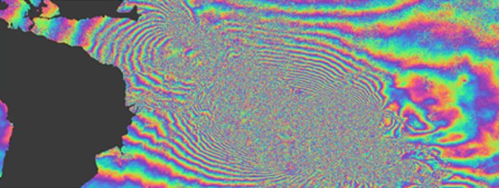
For example, the resolution of a multi-looked Sentinel-1 SAR image is roughly 20 x 5 m. This means that a rectangle of 20 x 5 meters on the ground is represented by a single pixel in the SAR image. And the brightness of this pixel will be decided by the backscatter of all objects contained within this rectangle on the ground. So, in the end, each pixel in a SAR image contains amplitude (characterized by intensity) and phase (characterized by change) information. Then we Combine two separate SAR images of the same scene to form an interferogram which represents the change by showing the phase difference between two SAR images.

Advanced InSAR Algorithms: In Search of more accurate deformation rates
The problem occurs when this information in an interferogram contains reflection of the radar waves from a ground element which, although changing, cannot be interpreted as the deformation (eg. vegetation change, variation in atmospheric conditions).
To get accurate deformation rates in low-rate deformation areas, it is essential to estimate and remove other phase components, such as atmospheric contributions. For this reason, specific InSAR algorithms were developed.
So instead of calculating the phase change in the whole pixel, this approach utilizes a stack of interferograms spread over a period of time to identify those points or scatterers showing reliable and stable backscattering mechanism over this time period and measure the deformations in such points. The backscattered signal from these points shall be stable and constant for a longer period.
The aim is to identify reliable points in which there is reliable and stable backscattering.
In order to identify these reliable points, we use Coherence which is a measure of the phase noise in the interferogram. It can be measured spatially, by measuring the stability of phase relationship between neighboring pixels and temporally by measuring the stability of phase behavior of a pixel over time. If corresponding pixels in image pairs are similar, correlation is high, and coherence is high. The converse is true. If corresponding pixels are not similar, the phase will vary significantly, and coherence will be low.
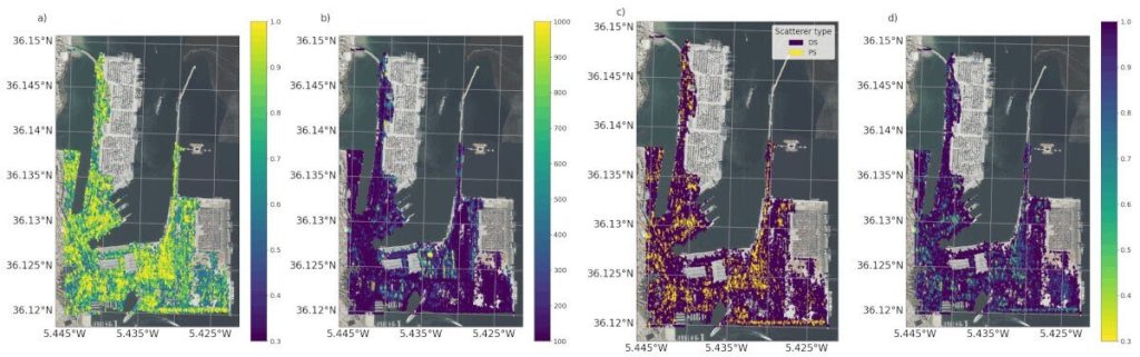
To obtain a significant number of measurement points we can exploit signal returns from two families of ground measurement points on the Earth’s surface.
- Permanent Scatterers (PS): radar targets characterized by high reflectivity values, generating very bright pixels in the SAR scene, usually corresponding to individual man-made structures
- Distributed Scatterers (DS): radar targets usually corresponding to many adjacent pixels in the SAR image, all exhibiting a very similar radar signature and where temporal decorrelation phenomena, though present, still allow the retrieval of displacement data usually corresponding to vast areas exhibiting homogenous phase behavior.
PS-InSAR: Persistent Scatterer Interferometry
The Persistent Scatterer Interferometry (PSI) technique is one of the earliest InSAR approaches that involves identifying pixels that have a strong and constant reflection over a long period which is named Persistent/permanent Scatterers (PS).
PS are identified by high coherence or correlation.
PS InSAR technique uses a large stack of interferograms covering the same area to identify stable ground points that reflect radar signals consistently over a long period of time, typically over several years. These stable points are usually found on man-made structures such as buildings, bridges, or on natural features like rocks, cliffs, and bedrocks.
The PS technique relies on identifying a large number of radar reflections from the same point and then using these observations to estimate ground deformation over time.
PS-InSAR technique is very effective for measuring surface deformation over urban areas and other man-made structures. Areas characterized by physical change, e.g., vegetated areas, water bodies, shifting dunes, construction zones, or geometric distortions caused by steep terrain slopes, will inherently have fewer PS. Also, a highly bright PS in an urban area can dominate its adjacent pixels beyond the pixel corresponding to its real location.
The main drawback of this method was the lack of density of points in non-urban areas. It is not suitable for areas that suffer from temporal de-correlation, e.g., vegetated areas or rapidly urbanizing areas.
PS-InSAR is a good options for measuring deformations in urban areas. However, it is not recommended for vegetated or rapidly urbanized areas.
Such areas lack stable points or structures which can be used for measurement.

The lack of points where deformation can be measured led to the development of new methods with less strict criteria for the inclusion of measurement points.
DS-InSAR: Distributed scattering interferometry
Distributed Scatterer (DS) InSAR technique, uses a dense network of scatterers, such as vegetation, to estimate ground deformation.
This technique is useful for measuring deformation over large areas, such as agricultural fields and forested regions, where stable reflectors are scarce.
DS-InSAR is a good option for measuring deformations in forested regions.
DS-InSAR uses a large number of point-like scatterers that are assumed to be randomly distributed over the scene. By tracking the radar signal phase changes over time at each scatterer, DS-InSAR can estimate the deformation of the ground surface.
Unlike dominant PSs, the DS pixel normally contains a coherent sum of individual small scatterers.
The interference of these small scatterers causes the variation in the returned signal of the pixel, which gives rise to temporal and geometrical decorrelations. The conventional DS usually covers several pixels with similar statistically homogeneous behaviors. It is possible to get enough coherence by processing these DSs statistically.
Differences between PS-InSAR and DS-InSAR
PS-InSAR is suitable for measuring deformation over man-made structures and other stable points, while DS-InSAR is used for measuring deformation over large areas with sparse or random scatterers.
We can use a combination of PSs and DSs to significantly increase the density of measurement points.
Workflow developed by Detektia for InSAR processing of PSDS
To conclude the article, we would like to share a new open-source workflow for InSAR processing of Persistent and Distributed Scatterers, developed by Detektia and published in Remote Sensing, one of the leading scientific journals in the field of remote sensing.
At Detektia, we maintain a close connection with the academic world. We are a spin-off of the Topography and Geomatics Laboratory at the School of Civil Engineering (UPM). Our team, composed of PhD holders and doctoral candidates, regularly publishes in high-impact scientific journals such as Remote Sensing.
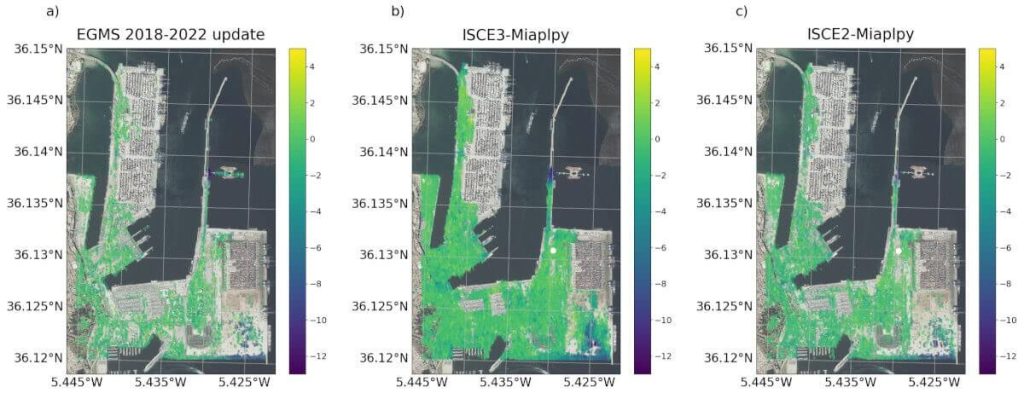
The evaluation of the algorithm presented by Detektia was carried out over the Port of Algeciras, a major European maritime hub, and the results were compared with data from the European Ground Motion Service (EGMS) project.
A novel aspect of the article is the use of Sentinel-1 images processed to Level 2, known as Coregistered SLC. Starting the InSAR processing with a coregistered image stack offers several advantages:
- Simplifies the InSAR processing workflow.
- Enhances the interpretability of intermediate products, which can be directly loaded into a GIS
- Reduces geolocation errors of InSAR points.
By working with coregistered scenes from the early stages of InSAR processing, we can easily visualize intermediate results in a GIS, as shown in the image.
This information can be highly valuable for infrastructure managers, as it facilitates the interpretation of InSAR deformation time series. Moreover, by simplifying the processing workflow, it broadens access to InSAR analysis—even for engineers without specialized training in remote sensing.
The work is based on a PSDS approach that incorporates the phase linking technique, which combines the phase information from multiple radar images to enhance spatial coherence and improve displacement detection accuracy.
This method enables long-term coherence retrieval over distributed scatterers, resulting in more robust and accurate analyses of structural stability.
The processing chain generated very high spatial coverage. The results showed a 43 percent increase in spatial coverage over the Port of Algeciras compared to the data provided by the European Ground Motion Service EGMS.
To evaluate the spatial coverage of the InSAR technique more accurately, objectively, and independently, a 30 x 30 meter grid was used.
If you’re interested in exploring the topic further, you can read the full article here: https://www.mdpi.com/2072-4292/16/21/3966.
Bibliographic sources
- The SAR handbook: https://ntrs.nasa.gov/api/citations/20190002563/downloads/20190002563.pdf.
- Interferometric Synthetic Aperture Radar Phase Linking with Level 2 Coregistered Single Look Complexes: Enhancing Infrastructure Monitoring Accuracy at Algeciras Port: https://www.mdpi.com/2072-4292/16/21/3966.
We sincerely hope you find this article useful. If you have any questions or just want to send us a message, please do not hesitate to leave a comment below ↓↓↓